3D-printed rocket nose cone: fit and recovery checks
A 3D printed rocket nose cone can match the body tube label and still bind halfway in. The shoulder may have a raised seam, a widened first layer or a shape that changed during printing. A cone that slides freely can have another problem: an attachment loop with a crack at its base, or enough extra mass to make the original flight model inaccurate.
Check the finished part against the specific rocket, not just the downloaded file. Start with the shoulder, then weigh the complete cone assembly and inspect the recovery connection required by the design. These are inspection steps, not a qualification test. They cannot establish that an unfamiliar printed part is suitable for flight.
This guide concerns filament-printed replacement cones. For material selection and the distinction between bench tools and flight components, use our guide to 3D-printed rocket parts. Use these checks to identify corrections and questions for the designer before installing the replacement.
Confirm what the cone was designed to replace
Keep the kit instructions and the cone designer’s documentation beside the part. Check the intended tube product, model revision, shoulder length and recovery arrangement. A file described as fitting a nominal tube size does not tell you whether it matches your supplier’s tube or a modified kit.
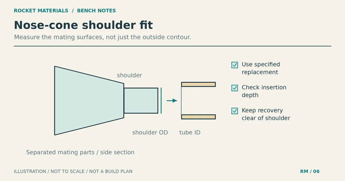
Separate the outside profile from the shoulder. The visible base of the nose meets the tube’s outside diameter; the shoulder slides inside the tube. Our body tube size chart explains those dimensions without assuming similarly named products are interchangeable.
Check whether the print requires a separate base, insert or other specified component. An incomplete assembly can look convincing on the bench. If the file has no documented recovery attachment or intended operating configuration, treat it as a fit prototype while you seek design review. Adding a hole or screw eye yourself changes the design; it does not fill a harmless gap in the instructions.
Measure the printed shoulder before changing it
Use calipers gently so you do not squeeze a thin paper tube or printed shell. Measure the tube opening in different directions and the shoulder at several positions along its length. Note where the seam runs and which end faced the print bed. A single diameter reading can miss an oval shoulder or a local ridge.
With no motor or ignition hardware installed, try the empty tube first. Insert the cone gently and stop when it catches. Record the insertion depth rather than forcing it past the obstruction. If the design permits different rotational positions, turn the cone and repeat the check. A change in resistance can help locate a high spot, although it does not prove which part is at fault.
| What you notice | What to inspect | What to avoid |
|---|---|---|
| The shoulder catches as it enters | Raised first-layer edge, brim residue, support scars or a damaged tube lip | Forcing the print through the opening |
| It starts freely, then binds deeper in | Diameter along the shoulder, an offset layer, internal glue or the shock-cord mount | Sanding the whole shoulder before locating the contact |
| Resistance changes when you rotate it | Seam height and roundness of both mating parts | Assuming the nominal tube size settles the question |
| It fits empty but binds when packed | Trapped cord, shroud lines, hardware and available packing space | Removing plastic to compensate for pinched recovery gear |
| The cone rocks or seats crookedly | Ovality, an uneven seating surface, damage or incorrect geometry | Using tape to hide a distorted print |
Prusa describes elephant foot as a first layer that spreads wider than intended. If that layer lies on the shoulder, the resulting lip can interfere with fit. This explains a possible defect; it does not supply a universal clearance for rocket parts.
For a conventional friction-fit model, the Estes technical manual, page 8, says the nose should separate easily without falling off when the rocket is inverted. It also tells builders to check for trapped lines before adjusting the fit. Use that as context, not as a force specification or a replacement for current kit instructions. Other retention arrangements need their own criteria.
Distinguish cleanup from a defective print
A small burr and a shifted section of shoulder need different decisions. Remove accessible brim or support residue only as the part’s instructions allow. If light surface cleanup is permitted, work on the identified contact area, remove dust and check the fit again. Keep the mating shoulder free of unwanted finish buildup and repeat the check after painting has fully dried according to the finish instructions.
Do not keep sanding until a badly mismatched cone happens to enter the tube. You may remove material the design depends on. Whole-model scaling is another poor substitute for a documented fitting adjustment: it changes the outside profile, shoulder length and attachment geometry as well as the diameter.
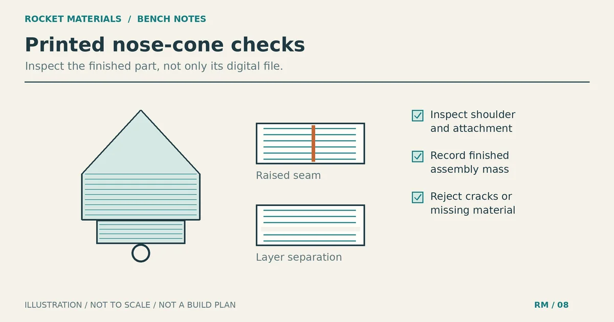
Inspect the entire shoulder and the base under good light. Set aside prints with cracks, separated layers, missing material around the attachment or obvious distortion. Prusa’s layer-shifting guide explains that shifted layers no longer occupy their intended positions. Sanding away the protruding edge does not restore the original geometry.
A shallow surface mark may be cosmetic, but an opening through the shell or a crack at a loop root deserves a different response. Do not fill it with glue or paint and count the part as repaired. Correct the manufacturing problem and obtain a replacement consistent with the reviewed design. A clean surface still cannot show whether hidden layer bonding or internal features are adequate.
Update mass and balance before trusting the simulation
Weigh the cone as it will be assembled, including its specified base, attachment hardware, cured adhesive and finish. Compare complete assemblies if you are replacing a stock cone. A slicer’s filament estimate leaves out finishing and separately installed parts.
Record the mass rather than assuming a hollow print must be lighter. A heavier replacement near the nose tends to move the rocket’s center of gravity forward, but that does not automatically make the modification acceptable. The complete rocket’s mass distribution and flight configuration still need checking.
Update the flight model with the actual geometry and measured assembly mass. If you use mass or center-of-gravity overrides, understand what each override includes so you do not count hardware twice or leave an old stock-cone value active. Measure the finished rocket’s balance in the configuration being evaluated and reconcile it with the model.
OpenRocket’s simulation documentation specifically warns that downloaded models may contain overrides that do not match your rocket. It covers launch-guide departure speed, deployment timing and ground-impact warnings. Re-run the intended configuration after changing the cone and review those outputs, not altitude alone.
For the same canopy and conditions, added recovery mass tends to increase descent speed. Revisit the parachute sizing and descent checks using the new mass. Neither a favorable stability result nor a gentle predicted landing proves that the printed attachment will survive deployment.
Inspect the recovery connection the design actually specifies
Trace the connection from the cord into the cone assembly. The load must reach the intended supporting structure through the specified loop, base or hardware. Check that every required piece is present and assembled in the documented orientation. A hole in a printed shell is not, by itself, a recovery anchor.
The Estes manual’s screw-eye instructions on page 4 concern a balsa nose cone or adapter. Do not transfer that method to a thin printed shell. Likewise, a smooth-looking integral loop does not establish its strength. Use the cone’s own reviewed attachment arrangement, not hardware chosen because it fits through the opening.
- Inspect the loop root and the surrounding base for cracks, voids or separated layers.
- Compare separate-base engagement, hardware placement and any specified adhesive joint with the design instructions.
- Check cord-contact surfaces for burrs or support remnants that could abrade the cord.
- Confirm the installed connection remains accessible for inspection and does not obstruct the shoulder’s intended insertion.
Our shock-cord mounting and inspection guide covers the broader system. This check is about whether the replacement cone preserves that system’s intended attachment and clearance.
Follow the manufacturer’s inspection or test procedure if one exists. An improvised hand pull has no defined load and cannot qualify the connection. If the attachment lacks documentation, ask the designer or kit manufacturer for guidance and keep the print out of the flight assembly until the uncertainty is resolved.
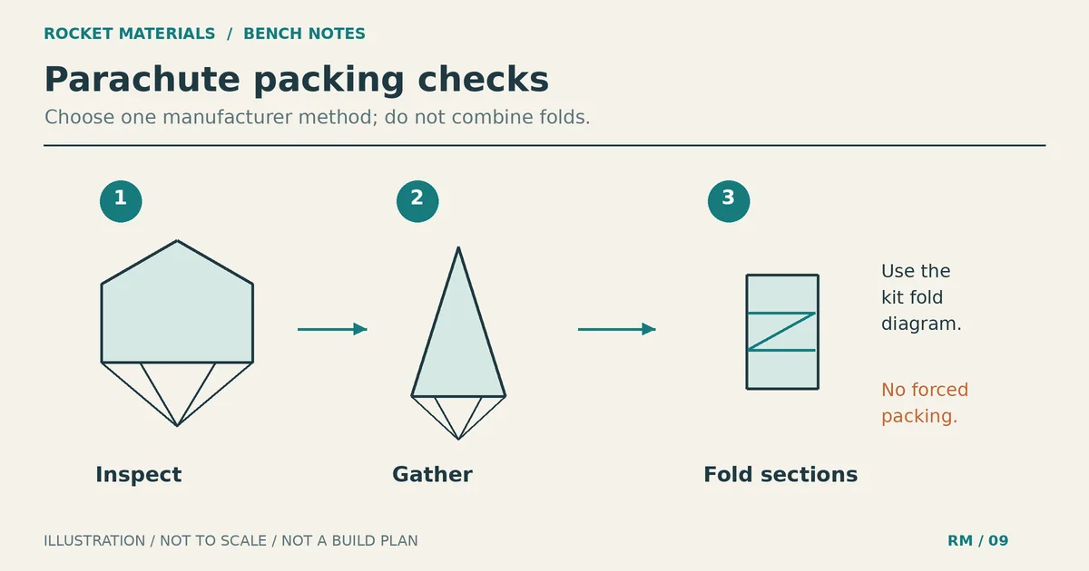
Finally, dry-pack the specified recovery gear and protective components with no motor or ignition hardware installed. Check that the cone seats without trapping lines and that its base or hardware does not crowd the bundle. Follow the kit’s packing and heat-protection instructions. OpenRocket’s recovery-system guidance explains why lightweight recovery components need protection from ejection heat. A printed base is not a substitute for that protection.
Keep a record with the part
Label the cone or its storage bag with the file revision and print record. Note shoulder measurements, any permitted cleanup, finished assembly mass and the attachment instructions used. Record the simulation file you updated and any unresolved fit or structural questions.
Use a clear disposition: rejected print, fit prototype, awaiting design review, or inspection completed against the documented design. Completing this checklist means you recorded the checks; it is not a flightworthiness claim. Before launch, follow the current kit directions and applicable range review. After recovery, inspect the shoulder and attachment again before considering another flight.