
3D-printed vs balsa model rocket fins: how to choose
Balsa is a good starting point when a kit calls for sheet fins. Printing earns its keep when the shape needs a feature that’s awkward to cut and assemble from wood, or when you want another copy of a design you already checked. Neither method makes a fin flight-ready by itself. Material, outline, print orientation or wood grain, root attachment and expected speed all matter.[5][7]
If you’re building a kit, follow its fin material, geometry, adhesive and motor instructions. A printed replacement is a design change, not a like-for-like swap simply because its silhouette matches.
3D-printed vs balsa fins at a glance
| Question | Balsa sheet | FDM-printed polymer |
|---|---|---|
| What controls mass? | Actual sheet density, thickness, outline and finish | Sliced volume, filament, walls, infill, supports and finish |
| What shapes are convenient? | Flat fins and hand-shaped edges | Repeated contours, integrated locating features and printable internal cavities |
| What needs inspection? | Grain direction, cracks, root fit and bond | Layer orientation, thin sections, voids, root fit and bond |
| How do I estimate time and cost? | Nest the outline on the actual sheet; include cutting, sanding and finish | Slice the actual file on the intended machine; include supports, failed prints and post-processing |
| Does a material label establish a safe motor? | No | No |
There is no honest universal grams-per-square-inch or cost-per-fin comparison here: a 3D printed fin can be a thin shell or a nearly solid part, while balsa sheets and fin thicknesses vary. Compare the same design goal and record the finished masses, not just the unpainted blanks. Apogee’s material discussion treats weight, grain and shaping as trade-offs rather than a single winning stock.[7]
Where balsa makes sense
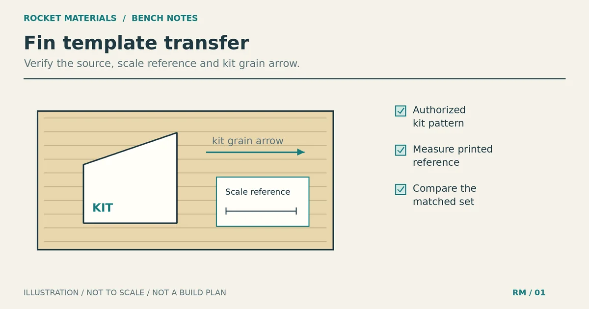
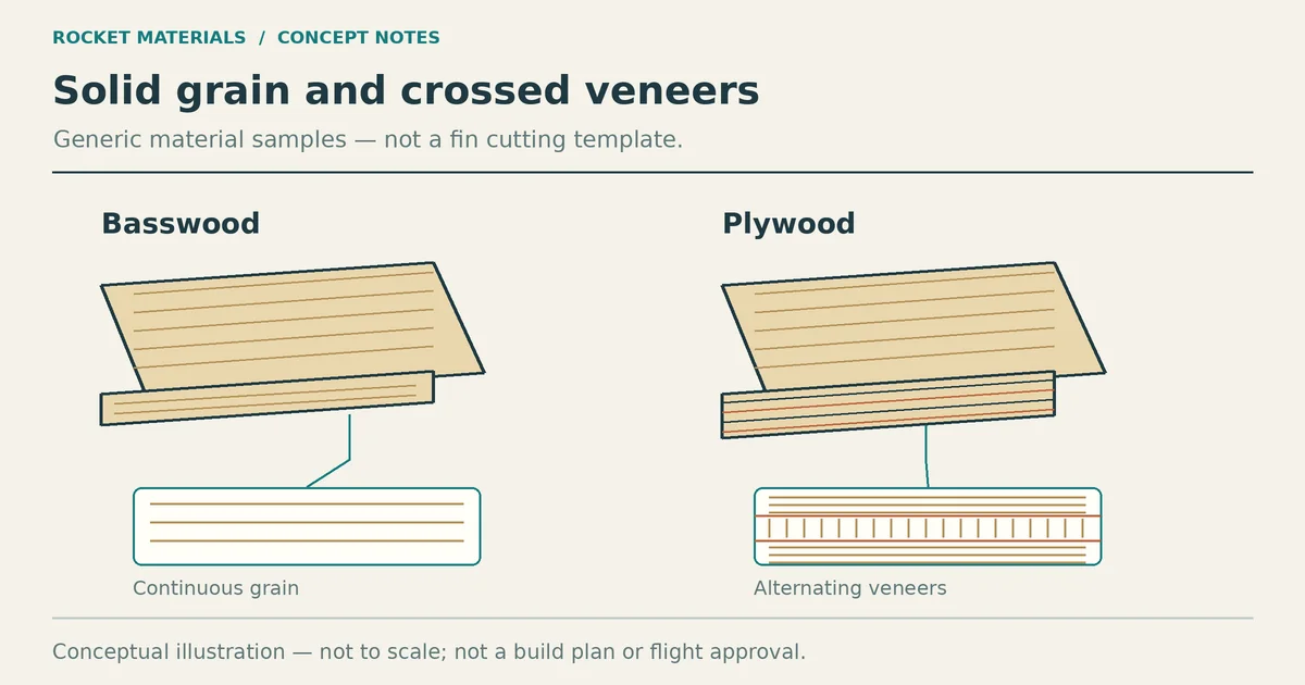
Balsa is easy to cut and shape with hand tools, and its grain matters. Inspect the actual sheet and lay out each fin according to the kit pattern; on a custom swept fin, “root to tip” and “along the leading edge” aren’t necessarily the same direction. Estes’s Design to Fly builder kit, for example, lists both 1/16-inch and 3/32-inch balsa sheets. Those are components of that kit, not generic thickness recommendations.[6][7]
Wood is convenient for a simple flat outline or a kit repair using the specified stock. It can dent, split or take up finish, so don’t equate the sheet mass with installed fin mass. If a fin is cracked or its root is loose, repair it according to the kit instructions and inspect the joint before another flight. Follow the kit’s grain marks rather than a universal angle prescription.
Where printing makes sense
A printer can reproduce an integrated locator, a curved exterior or several identical copies from one file. Identical files do not guarantee identical finished parts: filament, calibration, print settings and post-processing still vary. A printed fin can also be heavier or weaker than you expect around a thin root or at a layer interface. Check the actual slice, finished mass and root structure before treating a geometry as reusable.
PLA, PETG and ASA are different choices
Prusament describes PLA as easy to print but brittle and poorly suited to heat and prolonged outdoor exposure; its material page lists a 55 °C temperature-resistance value and says strength begins to fall above 60 °C. That number is not an ambient-temperature cutoff for a rocket, nor proof that a particular fin will deform on a particular pad.[1]
Prusament describes PETG as less brittle, more flexible and more heat resistant than its PLA, with strong layer adhesion; its material page lists 68 °C temperature resistance. It may be worth evaluating for a mechanical part, but the figure does not qualify an adhesive joint, a thin fin or a flight near motor hardware. Keep a printed fin away from direct exhaust and inspect for heat distortion after exposure.[2]
Prusa describes ASA as UV- and heat-resistant, but also warns of warping and potentially harmful fumes during printing. It calls for a ventilated workspace and notes that an enclosure is needed for large parts. Outdoor suitability does not mean an ASA fin is structurally qualified for your flight.[3]
These are manufacturer descriptions of specific material families, not interchangeable numbers for every brand, color, print process or finished assembly. We have no measured pad temperature, heat-soak test or flight test for the fins in this article. Nylon and other engineering filaments are deliberately not ranked here without a named product and relevant data.
Don’t copy a slicer recipe as a safety rating
Walls, infill, layer height and bed orientation affect material use and the load path, but no “30–40% gyroid” setting guarantees fin strength. The old draft even recommended zero solid skins; that is not a validated flight design. Think about which way bending and torsion can load the root and whether a layer boundary, thin wall, tab or adhesive interface could separate. Slice with the actual printer and filament profile, inspect the preview for gaps, then print a sample and examine the physical part. If you cannot justify the geometry and joint for the expected load, use the kit fin or seek experienced design review.
For a lower-risk use of a printer, a non-flight alignment jig can help position balsa fins without placing printed plastic in the flight load path. Even for a jig, check the kit’s alignment marks rather than using a universal cant angle.
Compare your own fin sets before deciding
- Make the outlines comparable. Record span, root chord, thickness, mounting features and whether the wood fin needs reinforcement or the print needs supports. A rectangular area alone does not specify a printed fin’s volume.
- Weigh the actual finished sets, including sealer, paint, tabs and any reinforcement. Record where the extra mass goes; tail mass can change the loaded center of gravity and stability.
- For cost, use the price of the sheet actually consumed or the slicer’s estimated filament mass times the price of your spool. Record usable nesting, failed prints, power and consumables if they matter to you. For time, compare a complete cut/sand/finish workflow with sliced print time plus setup, support removal and finishing. We have not run either workflow as a controlled test.
- Check the build as a system. Use the actual motor and loaded mass to evaluate stability and predicted speed; examine the fin and root joint for bending and flutter concerns. Apogee’s flutter discussion uses fin geometry, material properties and atmospheric conditions, not motor letter alone. A generic material data sheet is not necessarily an appropriate stiffness value for your printed orientation.[5]
- Follow the applicable launch rules. The NAR Model Rocket Safety Code calls for lightweight non-metal fins, certified commercial motors, a stability check when an untested rocket’s safety is uncertain, and a recovery system that returns it safely. High-power motors have separate certification requirements; NAR puts H/I in Level 1 and J–L in Level 2, with some F/G motors also requiring Level 1. No part of this guide approves a motor or design.[4][8]
Common questions
Are PLA or PETG fins safe on a D, G or H motor?
The letter is not a fin-strength test. It does not tell you the fin span, maximum speed, print orientation, root joint or heat exposure. Prusa’s material properties can help you shortlist a filament, not authorize a flight.[1][2][5] For a kit, keep to the manufacturer’s specified construction; for a custom build, check the whole design and have it reviewed if the loads are beyond what you can evaluate.
Are printed fins always heavier than balsa?
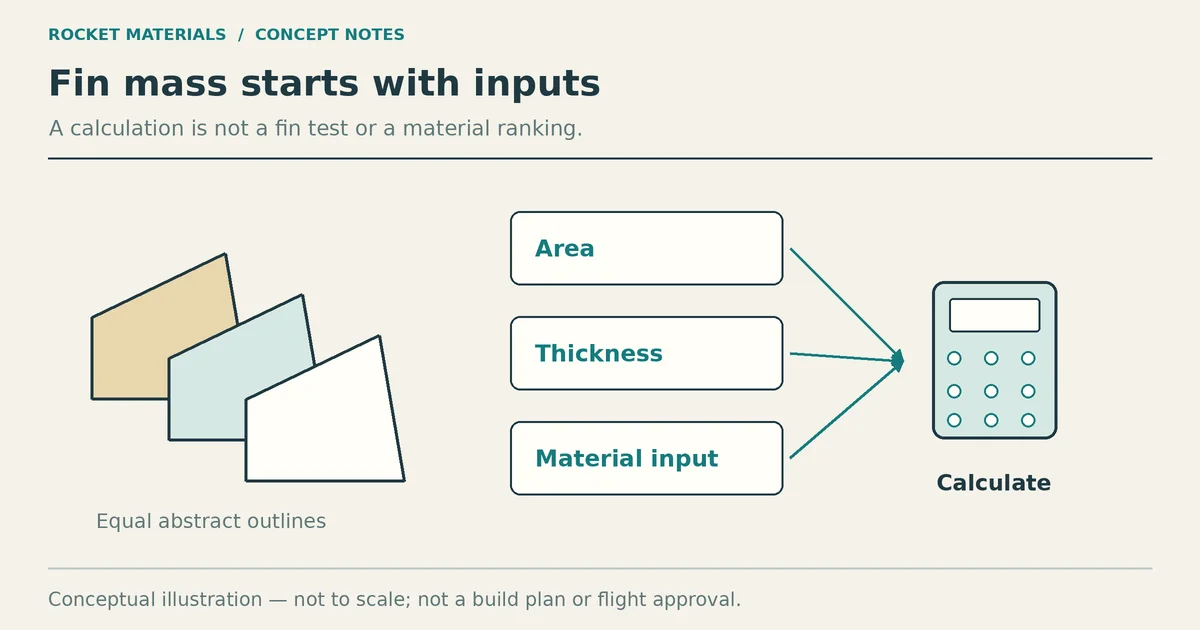
Not necessarily for every design, but don’t infer equal mass from equal outline. Balsa thickness and density vary, and a slicer can put very different amounts of polymer inside the same silhouette. Weigh completed sets and recheck stability with the actual motor. The earlier claimed eightfold ratio had no matching test record and has been removed.
Is a drop test enough to qualify a printed fin?
No. A landing impact may reveal one weakness, but it doesn’t reproduce aerodynamic bending, torsion, flutter or heat exposure in flight.[5] Inspect the fin, simulate the expected flight and assess the load path into the airframe; treat damage or layer separation as a reason not to launch until the design is repaired or revised.
Should I print the whole fin or just an alignment jig?
For a straightforward kit with balsa fins, the jig is often the less intrusive use of a printer. If the fin shape or integrated mount is the point of the project, printing may be useful, but the printed root, bond and changed mass need their own checks. No material change is a blanket flight clearance.
The choice is less about which material “wins” than whether you can account for the finished fin and its joint on this rocket. Start with the kit specification when there is one. For a new design, measure what you make and get the assembly reviewed before flight if you cannot establish its margins.
Commerce note: This guide contains no affiliate or tracked purchase links. Manufacturer pages below are technical sources, not product endorsements; no firsthand fin weighing or flights are claimed.
Sources
[1] https://prusament.com/materials/pla/
[2] https://prusament.com/materials/prusament-petg/
[3] https://help.prusa3d.com/article/asa_1809
[4] https://www.nar.org/ModelRocketSafetyCode
[5] https://www.apogeerockets.com/Peak-of-Flight/Newsletter615
[6] https://edu.estesrockets.com/products/design-to-fly
[7] https://www.apogeerockets.com/Advanced_Construction_videos/Rocketry_Video_403
[8] https://www.nar.org/HPRCertification