Tube fins for model rockets: design and build checks
Tube fins give a rocket a different look: open cylinders sit around the rear airframe where you would normally expect flat fins. They can also change the work at the bench. Instead of tracing balsa outlines and sanding matching edges, you arrange tube sections and check their glue contacts.
For a first tube-fin rocket, start with a kit and its instructions. A neat circle of tubes is not proof of stability, and a convenient piece of spare tubing is not automatically a suitable replacement fin. The useful questions are more specific: do the supplied tubes match the layout, are their axes straight, and can the launch guide pass without binding?
The checks below use LOC Precision’s Cyclotron instructions as a worked example. They explain what to inspect, not how to design an untested rocket from loose parts.
What tube fins are, and what they do not tell you
A tube fin is an open tube mounted outside the main airframe, generally with its length running along the rocket. The tube wall provides the fin surface. Several individual tubes around the body are different from one large ring surrounding the tail; do not transfer a ring-tail plan to a tube-fin build just because both have circular openings.
Commercial examples show that the same broad configuration can belong to very different rockets. Quest’s Totally Tubular product page describes a beginner kit with colored tubes, self-adhesive decals and streamer recovery. LOC’s Cyclotron page lists a larger kit with rail guides and parachute recovery. Those are examples, not interchangeable recipes.
The appeal is practical if you would rather assemble supplied tubes than cut flat fins. That does not establish a universal advantage in weight, drag or durability. Compare complete kits and the work their instructions require. A tube-fin model still needs a sound motor mount and a suitable recovery system.
Choose an instruction-defined configuration
Before buying replacement tubes or opening the glue, find the manual for your exact kit version. Record the tube-fin count, supplied tube lengths, placement reference and launch-guide arrangement. If the manual covers more than one size, identify which parts list and steps apply to yours.
LOC’s revision 2 Cyclotron instructions cover both its 3-inch and 4-inch kits. Both parts lists specify six tubular fins. Step 6 groups them into three pairs before mounting those pairs around the airframe. That is the arrangement this example follows; it is not a rule that every tube-fin rocket needs six tubes.
Do not shorten a fin to clear hardware, change its diameter to use a leftover part, or omit a tube because the remaining set looks evenly spaced. Those changes depart from the documented configuration. Ask the kit maker about replacements rather than inventing a fit correction.
For replacement identification, our body tube size chart explains outside and inside diameter. It is a parts reference, not a tube-fin design chart. Match the actual supplier and product, not just a familiar nominal label.
Dry-fit tube fins before committing to glue
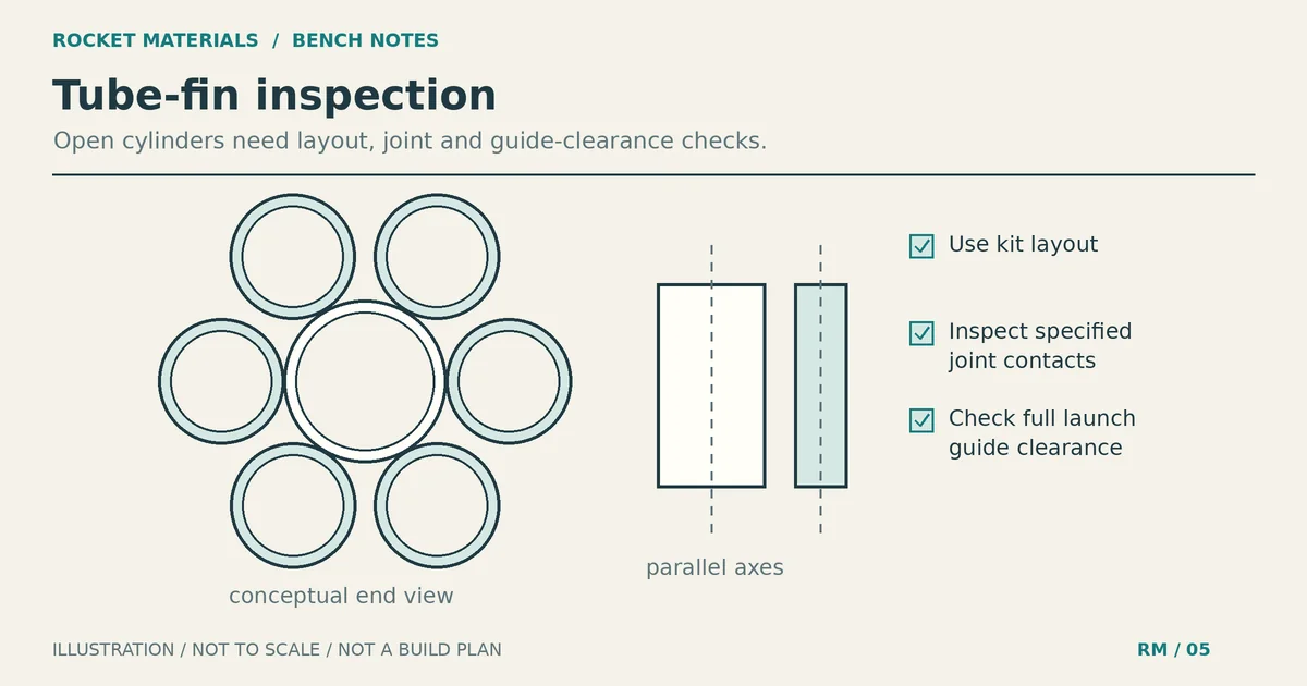
A dry fit is an assembly without adhesive. It gives you time to compare the parts with the manual while mistakes are still easy to undo. Keep the layout in view rather than relying on a photograph of the finished rocket.
| Check | What to compare | When to stop |
|---|---|---|
| Parts | Each tube against the kit list and supplied set | A tube is missing, damaged or apparently different |
| End position | The front and rear edges against the manual’s references | A tube sits ahead of or behind the intended position |
| Longitudinal alignment | The tube axes against the intended airframe direction | A pair twists or leans relative to the layout |
| Contact areas | Tube-to-tube and tube-to-body contacts shown in the manual | A visible mismatch prevents the specified joint |
| Launch clearance | The complete guide path against the fin layout | The rod or rail would touch or bind on a fin |
These are workmanship checks, not measured flight tolerances. There is no universal acceptable gap or skew angle supplied here. A damaged rim, flattened tube or uncertain replacement needs investigation before assembly, even if you can push the set into an attractive shape.
Check both views. Looking from the rear helps you compare the arrangement around the body; looking along the side helps you catch a tube pointing away from the intended direction. The fin alignment guide covers that distinction without treating appearance as a stability test.
Build the tube-fin joints the manual specifies
In Cyclotron step 6, LOC starts the pairs on a flat surface with their edges even. A light lengthwise bead of epoxy joins each pair. After that joint cures, the instructions add a fillet in the valley between the tubes, then repeat the fillet on the opposite side after curing.
This sequence matters when you handle a pair. The manual warns that the initial thin joint can be fragile before the fillets are added. Support the assembly as directed; do not use an uncured pair as a convenient handle for turning the rocket.
For mounting, LOC uses a tube fin to mark its height on the airframe, then calls for surface preparation. The airframe and fin sets stand with their bottom edges even on a flat surface. The builder marks and scuffs the contact points before attaching the sets. Read the PDF’s illustrations alongside the text so you can identify the intended fillet locations.
LOC then tacks one pair in place and lets the epoxy cure before moving to the next. Once the sets are mounted, it calls for the remaining fillets. Do not replace this with a large pool of glue under the whole assembly. Apply the specified joints and keep the guide path clear.
Use the kit’s adhesive guidance and the adhesive manufacturer’s mixing, protective-equipment and cure instructions. A quick-setting label is not permission to load a joint immediately. Our adhesive selection and cured-mass guide explains why saving glue weight comes after choosing a suitable joint, not before it.
Keep the launch rail clear of the tube fins
Launch-guide clearance deserves its own check because a symmetrical fin set can still obstruct the launcher. Cyclotron step 5 notes that spacers may be needed beneath the rail buttons to prevent the rail from binding on a tube fin.
Step 6 also specifies that the center of a tube fin must align with the airframe and rail-guide centerline: the launch rail has to slide through that tube fin. This is a kit-specific relationship. Do not decide where to put the first pair solely by choosing the side that looks best.
Plan that path during the dry fit. After assembly has cured, check travel on compatible launch hardware with the rocket unpowered and no initiator installed. Look for interference along the whole travel, not just where the buttons first enter the rail. If it binds, stop and resolve the mismatch using the maker’s directions.
Do not notch a tube fin, relocate a button or substitute a different guide to make the problem disappear. Those changes need assessment. The Cyclotron example does not authorize putting a launch lug inside a fin on another kit.
Treat drag and wind claims with caution
Tube-fin discussions often promise straight flights or describe every design as slow and draggy. Neither statement is enough to select a motor or approve a launch.
Allison Van Milligan’s 2013 NARAM report, Drag on Tube Fins, tested several configurations in a low-speed wind tunnel. The report’s fitted trends showed increasing drag with tube length. Its equal-surface-area comparison with flat fins used an extrapolation, not a directly tested matched pair. It also identifies an anomalous baseline measurement that produced some negative calculated tube-fin drag values, and calls for further testing.
That is useful evidence that geometry matters. It does not supply a universal drag coefficient, an altitude prediction for your kit, or proof that tube fins prevent weathercocking, which is a rocket turning into the wind.
Keep the manufacturer’s flight guidance attached to the exact build. Cyclotron’s preflight instructions call for simulation and a stability check in flight-ready condition. Its listed motor suggestions and center-of-pressure positions belong to that design; they should not be copied onto a smaller home-built model.
Changes in parts or finished mass need review before flight. If you cannot establish that the assembled rocket matches the intended configuration, consult the manufacturer or an experienced club safety officer. Adding nose weight by guesswork is not a substitute for that review.
Final inspection before taking it to the field
Once the adhesive and finish have cured, compare the rocket with its instructions again. Paint can hide a joint edge, so check the structure before finishing as well as afterward.
- Confirm every tube is present and in its specified position, with no loose joint, split rim or crushed section.
- Check the required fillets and make sure finishing materials have not obstructed the launch-guide path.
- Inspect motor retention and the recovery attachments under the kit’s directions.
- Check recovery packing and the intended separation points. External tube fins do not replace a parachute or streamer.
- Review the finished configuration, selected commercial motor and applicable launch requirements before flight.
The shock cord mounting and inspection guide helps with the recovery attachment check. Follow your kit’s specified anchor rather than drilling a generic attachment into a thin tube.
For model rockets, the NAR Model Rocket Safety Code requires certified commercial motors and suitable recovery, among other launch precautions. High-power flights have separate requirements in the NAR High Power Rocket Safety Code, including certification and checking stability before flight.
Start by laying out your kit’s tube fins beside its manual. Resolve any mismatch before gluing the first pair. Getting the configuration and launch clearance right at the bench is much easier than discovering a problem at the pad.