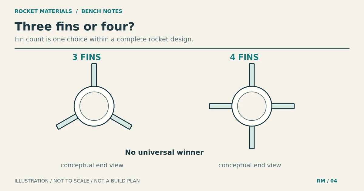
How many fins should a rocket have? Three vs four
How many fins should a rocket have? For a conventional model rocket, three or four can both work. If you’re building a kit, use the count and fin shape in its instructions. If you’re designing your own rocket, compare the complete three-fin and four-fin designs before cutting wood. Fin count alone does not tell you whether either version will fly safely.
Three fins mean one fewer part to cut, finish and attach. Four may fit the scale model you want to build, or work better with the fin dimensions your design needs. Neither count is a universal winner for stability or altitude. Compare the airframe and fin geometry with the finished mass and intended commercial motor included.
Three versus four rocket fins at a glance
| Decision | Three fins | Four fins |
|---|---|---|
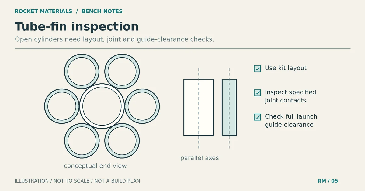
| Ordinary equal spacing | 120 degrees around the tube | 90 degrees around the tube |
| Identical individual fins | Fewer parts and less total fin area | More total fin area and fin-stock mass |
| Build work | One fewer fin and root joint | One extra fin to prepare and inspect |
| Stability | Must be checked with the full design and motor | Must be checked with the full design and motor |
| Good reason to choose it | Specified by the kit, or supported by your design comparison | Specified by the kit, scale layout, or your design comparison |
The area and mass comparison assumes the same individual fin outline, thickness and material. It does not mean a properly designed three-fin rocket always has less drag than a properly designed four-fin rocket. Once you change the fin dimensions, you’re comparing different complete fin sets.
Stability depends on where the forces act
A rocket’s center of gravity, or CG, is its balance point. Its center of pressure, or CP, is the effective location of the aerodynamic forces. For the conventional passively stabilized model rocket discussed here, the CP needs to be behind the CG, toward the tail, so a small disturbance produces a restoring tendency rather than a growing turn. NASA’s explanation of rocket stability illustrates this relationship.
The fins contribute to that aerodynamic response, but so do the nose and body. Fin span, chord lengths, sweep and position change the result. The same fin set on a different airframe is not automatically equivalent. The Estes Model Rocketry Technical Manual, pages 7-8, explains why fin size and distance from the balance point matter, and why the motor must be present when checking CG.
Adding a fourth identical aft fin changes both the aerodynamic geometry and the mass distribution. The extra fin may increase the aft set’s restoring contribution, while its weight pulls CG toward the tail. You need to check the combined effect. Counting fins skips that part.
A CP marker behind a CG marker is also not a complete launch assessment. You still need suitable flight behavior, sufficient speed as the rocket leaves its launch guide, sound construction and working recovery. There is no single stability-margin number in this guide that certifies every rocket.
What the extra fin costs in mass and drag
A fourth copy of the same fin adds its own mass. Its joint, filler and paint can add more. That matters because the added material sits near the tail, where it can change the balance of the finished rocket.
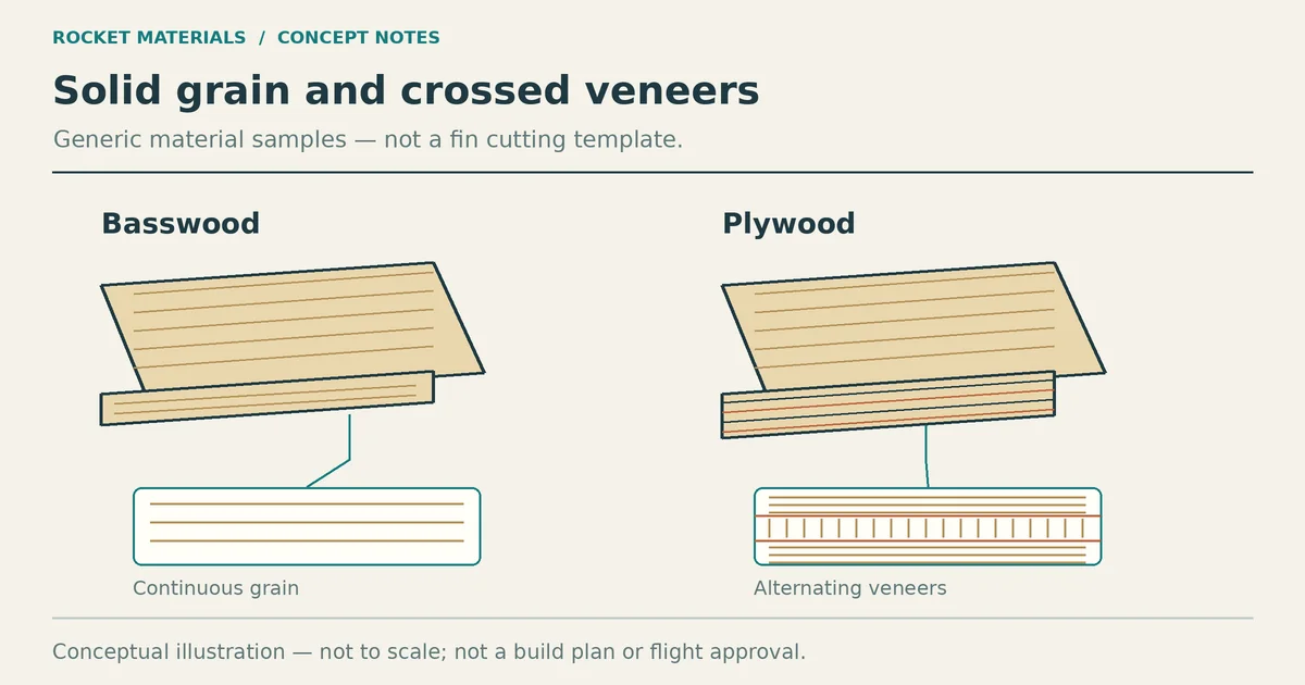
For a useful estimate, compare the actual fin sets rather than assuming every balsa or plywood sheet has the same weight. The calculated fin-material weight comparison covers area, thickness and density. Keep those inputs separate from fin count so you can see what caused the difference.
More fins also change the drag-producing geometry. An extra identical fin adds exposed surface and another body junction, but total drag depends on the complete shape, thickness, surface finish, flight speed and angle to the airflow. OpenRocket’s advanced simulation documentation describes its geometry-based aerodynamic calculations. It does not support a fixed altitude penalty for adding one fin.
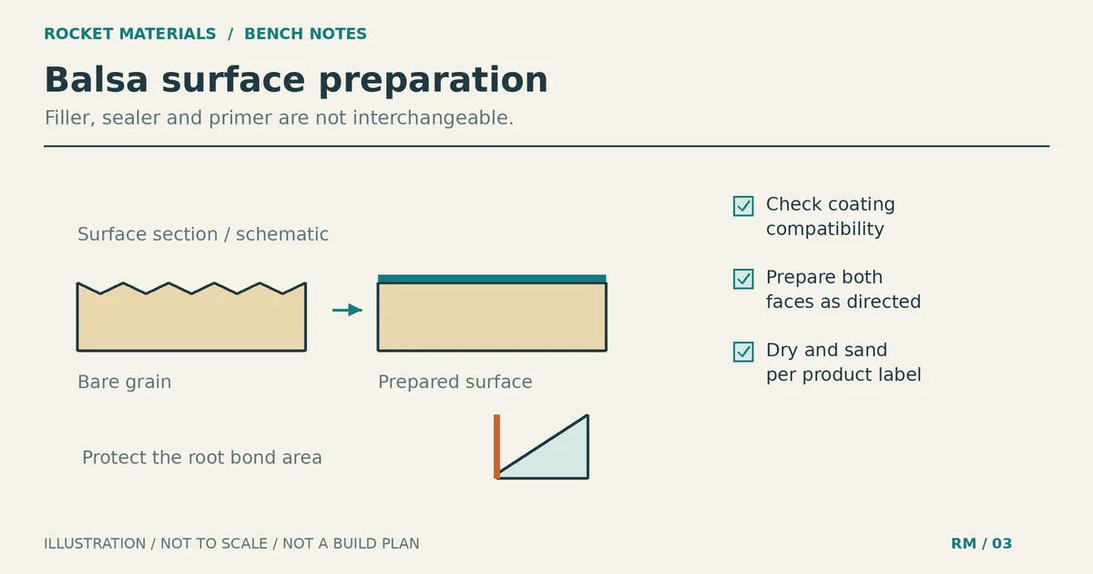
Do not leave adhesive and finish out of the model just because the wood looks light. Use the guide to measuring cured adhesive weight when checking the assembly. Choose the joint and adhesive required by the design first; saving mass is not a reason to weaken the attachment.
Compare three and four fins in two different ways
Keep each individual fin unchanged
Copy a design file and change only the fin count. Keep the outline, span, thickness, material and axial position unchanged. Use the same motor and launch conditions. Allow the model to account for the extra fin’s mass, and include the additional attachment and finish mass in a realistic location.
This comparison answers a narrow question: what happens when this particular rocket gains another copy of this particular fin? It can expose a balance change or performance trade-off. It does not establish the best count for all rockets.
Compare two independently designed fin sets
For a custom design, you may instead compare three larger fins with four smaller fins. Before changing either set, decide which motor you plan to fly and what the launch field allows. Keep the construction method and flight requirements consistent too. Then assess both versions against those same requirements.
Equal total fin area is not proof of equal stability. Changing span, chord, sweep or position changes the aerodynamic response, and changing material or thickness changes mass. Record those differences rather than describing the comparison as a count-only test. If one version comes out ahead, keep its geometry and motor configuration with the result. Another rocket may give a different answer.
Check the whole flight in OpenRocket
Build an accurate digital model before relying on a comparison. OpenRocket’s basic flight simulation guide recommends matching dimensions, component masses and the finished rocket’s balance. It also explains that the selected motor changes the model’s weight and center of mass.
- Enter the nose, tubes, complete fin geometry, motor mount and recovery components. Account for other installed hardware and its location.
- Select the actual intended commercial motor and its available delay. Do not treat the motor name as an optional detail.
- Save separate three-fin and four-fin versions. Check mass or CG overrides so an old setting does not hide the effect of a changed fin set.
- Use the same launch-guide length, site conditions and wind assumptions for both. Review warnings, guide-exit speed, deployment behavior and the CG/CP or stability plots through ascent.
- Compare more than a calm-air altitude figure. Check how each design behaves in realistic wind conditions within the applicable launch limits.
A stable rocket can still turn into the wind. NASA’s weathercocking explanation shows how relative airflow produces that turn and can reduce vertical altitude. Adding fin area is not a guarantee of a straighter vertical flight.
| Record for each version | Why keep it |
|---|---|
| Fin count, outline, span, thickness and position | Shows whether count was the only geometry change |
| Finished mass, CG and motor configuration | Keeps aerodynamic changes separate from balance changes |
| Launch guide and weather assumptions | Makes the two simulations comparable |
| Warnings, stability history and recovery results | Prevents peak altitude from becoming the only decision |
This article supplies a comparison method, not a set of simulated or flight-tested results. A simulation predicts the behavior of the model you entered. It does not inspect glue joints or prove that a flexible fin will survive the flight.
Keep kit instructions and build quality in the decision
For a first kit, finish the specified design rather than experimenting with fin count. Removing a fin from a four-fin kit changes the intended geometry; adding one to a three-fin kit changes geometry and mass. Either modification needs reassessment, even if the rocket still looks balanced.
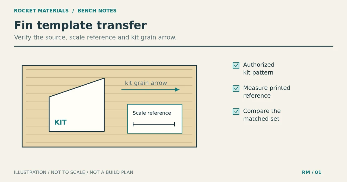
After choosing a count, placement remains a separate job. Follow the fin alignment guide for marking, jigs and inspection. Equal spacing does not excuse twisted fins, unmatched outlines or damaged joints.
Structural questions also need their own checks. Four fins are not insurance against losing one, and three fins do not make a weak attachment acceptable. The fin reinforcement guide discusses failure modes and the load path. Count alone cannot settle material, thickness or flutter concerns.
Can a rocket have two fins, more than four, or none?
With two ordinary flat tail fins opposite each other, a sideways disturbance can meet the fins edge-on. That arrangement does not provide the same restoring response in every sideways direction as a conventional three- or four-fin set. They are not a drop-in substitute for a kit fin set. Unusual configurations need analysis suited to their geometry.
More than four fins may fit a scale model or another design requirement. They still add geometry and mass that need assessment; a higher count is not automatically safer. Finless full-size launch vehicles are a different comparison. NASA notes that modern full-scale rockets often use pivoting exhaust nozzles for control rather than relying on fins.
For your next build, start with the instructions if it’s a kit. For a custom rocket, save both complete design versions, check them with the intended motor, then update the chosen model with measured finished mass and CG. Ask an experienced club reviewer to assess an unfamiliar configuration before launch. Choose the count from that design review, not from a rule that three is fastest or four is safest.