Model rocket launch lug: placement and alignment
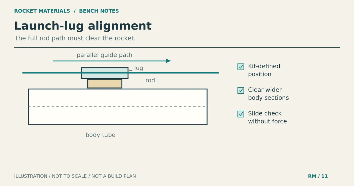
A model rocket launch lug can look straight on the workbench and still bind on the launch rod. Start with the kit’s specified position. The lug must run parallel to the body tube, with room for the rod to clear the whole rocket. If the kit uses two lugs, the same rod must pass through both without forcing either one sideways.
Do those checks before adding glue. A dry fit lets you catch a crooked lug or a payload section that blocks the rod while you can still move the parts. Once the joint has cured, fixing the position may mean replacing the lug and repairing the mounting surface.
What the launch lug does
The lug is the small guide tube that slides over the launch rod. It helps guide the rocket during the start of flight, before the fins can provide effective aerodynamic guidance. The Estes Model Rocketry Technical Manual, section 8, explains that role and calls for the lug to be parallel to the body tube.
A good-looking glue joint doesn’t prove that the guide works. A lug can be firmly attached but tilted, blocked with glue, or positioned where the rod hits something farther up the airframe.
Use the lug type, quantity and position shown in your kit instructions. There isn’t one distance from the tube end that fits every rocket. Don’t move a lug to a convenient empty spot or split it into two pieces because another model uses that arrangement.
Gather the parts and mark the specified position
You need the kit’s lug and any specified standoff, the recommended launch rod, a pencil, a ruler or tube-marking tool, and the adhesive called for by the kit. Keep the instructions beside the model rather than trying to remember a placement diagram.
The Alpha instructions currently linked by Estes tell builders to test fit all parts before applying glue. They also include a separate launch-lug attachment step. Follow your own kit’s drawing; an Alpha placement is not a template for a different rocket.
Transfer the kit’s launch-lug mark to the body tube, then extend its lengthwise reference line with the marking method the instructions recommend. Check that the line follows the tube instead of winding around it. Mark the specified fore-and-aft position too. The lengthwise line helps with direction; it doesn’t tell you where along the tube the lug belongs.
If you are also marking fins, keep the two jobs separate. Our fin alignment guide covers fin spacing and orientation. Here, the question is whether the rod has a straight, unobstructed path through the launch guides.
Dry fit the lug and check the complete rod path
Make this a cold bench check: leave out the motor and starter, and keep the launch controller disconnected. Support the rocket and handle the rod where its tip cannot injure someone. Don’t balance the model on an exposed upright rod to inspect it.
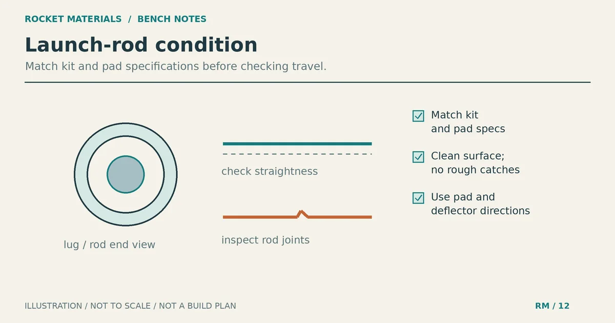
- Inspect the loose lug. Its ends should be open, and the tube should not be crushed, split or visibly distorted. Replace a damaged part rather than trying to make it usable with extra glue.
- Slide the loose lug onto the recommended rod. Stop if it catches. Check that you have the correct part and rod before changing either one. Estes’ launch-lug guidance specifically calls for pairing the lug with the rocket’s recommended rod so the model can move freely.
- Hold the lug at its marked location without adhesive. For two lugs, pass the same rod through both while holding them in their prescribed positions. Neither lug should need to bend or tilt to accept it.
- Check the rest of the airframe beside the rod. Include the nose cone, transitions and any enlarged payload section in their assembled positions. Look for a surface that contacts the rod even though the lug itself fits.
A loose lug may slide freely and still leave the rod rubbing against the rocket once installed. Hold it against the complete airframe at the intended location before deciding the fit is right.
Don’t confuse the body tube’s diameter with the lug’s rod compatibility. The body tube size chart helps identify airframe dimensions, but the kit’s launch instructions determine the guide and rod pairing.
Keep the model rocket launch lug parallel while attaching it
Prepare the bonding surface and apply adhesive as your kit directs. Support the body so it cannot roll while you position the lug. Set the lug on its marked line and sight along the body tube before the glue sets.
Estes gives that sighting check in section 8 of its technical manual. Look from more than one direction: a lug may appear straight from above while one end sits higher than the other. On a straight body section, its axis should follow the body’s lengthwise direction rather than pointing toward or away from the tube.
With two lugs, being individually parallel isn’t enough. Their openings must also share a common rod path. The dry fit should establish that path before bonding; check that neither part shifts as you attach it. Don’t leave the rod in wet adhesive as a makeshift clamp. Gluing the guide to the rod creates another problem.
If the lug moves while the adhesive is still workable, correct it before the joint sets. If it has already hardened crooked, stop and plan a kit-appropriate repair. Bending the rod or forcing the model over the misalignment doesn’t fix the joint.
When a standoff is needed
A standoff moves the lug away from the body tube so the rod can clear an obstruction. Section 8 of the Estes manual gives a large-diameter payload section as an example and specifies the assembly order: attach the lug to the standoff first, then attach that unit to the body.
Use the standoff supplied or specified for the design. Its height, shape and mounting location depend on the rocket’s geometry. A generic spacer height cannot account for every transition, lug or payload section, and stacking scrap material is not a verified substitute.
Dry fit the standoff assembly against the completed airframe before bonding. Check the lug’s direction and the rod clearance together. If the rod still hits the payload section with the specified parts in place, recheck the assembly against the drawing and ask the manufacturer about the mismatch.
For a design without a specified standoff, unexpected contact is a reason to review the design, not permission to invent a mounting arrangement. For two lugs, both guides must still share the same rod path after any specified offset.
Add fillets after the first joint dries
Estes’ launch-lug attachment instructions say to apply glue fillets after the initial lug joint has dried. A fillet is the bead of adhesive along the junction between the lug and its mounting surface. Follow the kit’s shape and adhesive instructions rather than burying the part under a large blob.
Keep adhesive out of the bore and away from the openings. Inspect both ends as you work. Fillets reinforce the intended joint; they cannot straighten a lug whose first bond has already cured at the wrong angle.
The manual identifies white glue as suitable for porous parts such as paper and balsa launch lugs, while the Alpha instructions list carpenter’s glue. That doesn’t make either adhesive right for every plastic or composite assembly. Our rocket adhesive guide discusses choosing glue by the joint materials and instructions, rather than assuming more glue is better.
Allow the assembly to dry or cure as directed before checking it on the rod again. Protect the bore during finishing and recheck afterward; primer or paint near an opening can change a fit that was acceptable before finishing.
Troubleshoot binding without forcing the rocket
| What you notice | What to check next |
|---|---|
| The loose lug won’t slide freely. | Confirm the prescribed lug and rod pairing, then inspect for damaged parts or contamination. |
| Each loose lug fits, but both together bind. | Check the shared rod path. One guide may be offset or tilted relative to the other. |
| The rod passes through the lug but touches the rocket. | Compare the assembled geometry and any specified standoff with the kit drawing. |
| The fit changes after finishing. | Inspect the openings for coating buildup. Avoid aggressive scraping that could split the paper guide. |
| The lug moves or its mounting surface is damaged. | Keep the rocket out of service until a manufacturer-appropriate repair or replacement is complete. |
A successful bench slide checks fit, not flight readiness. Before launch, inspect the lug and its attachment again, along with the rest of the rocket and launch equipment required by the instructions. If the model binds, the lug is damaged, or the mounting joint is loose, don’t launch it.
Before putting the glue away, compare the installed lug with the kit drawing one last time. Check its position, sight along its axis and confirm clearance with the actual recommended rod after the joint has dried. If something catches, resolve it at the bench before packing the rocket for launch.