Model rocket launch rod: size, clearance and care
A model rocket launch rod needs to match the rocket’s instructions and fit the launch pad securely. It also needs a clean, straight surface that lets the launch lug slide without catching. A rod can look fine in the bag and still have a rough joint that stops the rocket halfway up.
Start with the kit’s specified launch equipment, not the motor letter or the rocket’s body-tube diameter. Then check the rod itself and the complete path the rocket will travel. The checks below are for commercial model-rocket equipment; they don’t turn a small pad into a high-power launcher.
Match the launch rod to the kit and pad
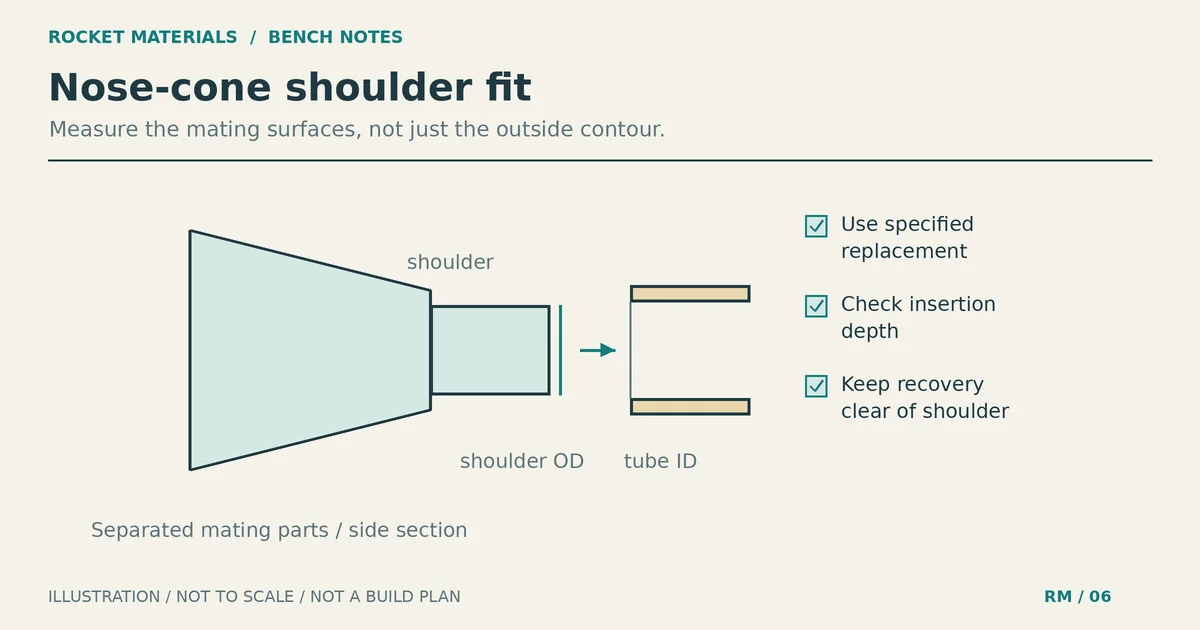
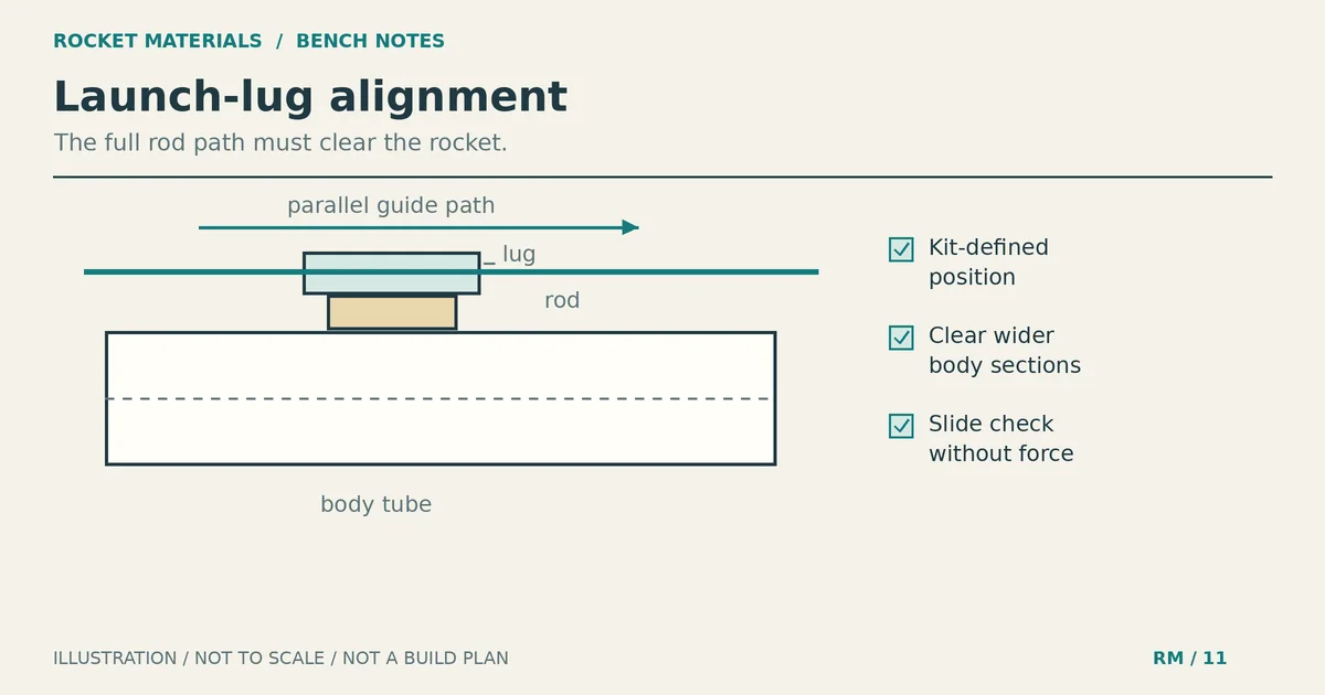
The launch lug is the small guide tube attached to the rocket. It slips over the launch rod, which guides the rocket during its initial movement. The lug and rod have to work together, but a loose fit alone doesn’t prove that you’ve selected the right equipment.
For a concrete example, Estes lists the Big Bertha, kit 001948, with a Porta-Pad II launch system and a 1/8-inch launch rod. Those are specifications for that kit. Don’t apply them to another rocket because it looks about the same size.
| Rod or listing | Diameter | Verified fit or length | What still needs checking |
|---|---|---|---|
| Estes 002243 two-piece rod | 1/8 inch | Estes specifies fit with Porta-Pad II, 2215. | The retrieved manufacturer text doesn’t state assembled length. Confirm the supplied rod and kit requirements. |
| Estes 002244 MAXI rod | 3/16 inch | Estes specifies Porta-Pad II, 2215, and Porta-Pad E, 2238. | The rocket must accept and specify this equipment. Manufacturer text retrieved here doesn’t state assembled length. |
| Apogee replacement-rod listing, model 07168 | 1/8 inch | Supplier lists an assembled length of 31.5 inches (80.0 cm), manufactured by Estes. | This is an attributed listing dimension, not a minimum for every model rocket or a verified dimension for every Estes package. |
The Porta-Pad II product page confirms that it includes a 1/8-inch rod and accepts the optional 3/16-inch MAXI. Its instructions use different mounting holes for those rods. Use the correct hole and fastening arrangement; don’t wedge an undersized rod into a larger socket.
Body-tube labels describe a different part. Our body-tube size chart helps with airframe fit, but a BT designation does not tell you which rod to buy.
Launch rod length isn’t a universal number
Use the length or complete launch system required by the kit manufacturer. If the instructions name a pad rather than a separate rod length, start with that specified system. If you need a replacement and can’t confirm its dimensions, ask the manufacturer before substituting hardware.
Keep rocket length and rod length separate when reading a product page. A kit’s headline length measurement usually describes the rocket. It is not automatically a launch-rod specification.
The Estes Model Rocketry Technical Manual explains why initial guidance matters: the rocket needs airflow over its fins before they can guide it. That doesn’t produce a single rod length or exit-speed rule for every combination of rocket, motor and weather.
Don’t shorten a rod for easier transport, leave it partly inserted to gain exposed length, or add an improvised extension. Follow the equipment’s assembly instructions. The length buried in the mount and the rocket’s starting position also affect how much guidance is available, so overall rod length alone isn’t a flight approval.
Inspect straightness and the assembled joint
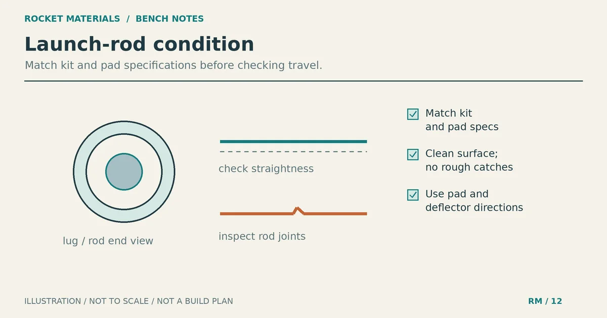
Check the rod before installing a rocket. Look along it from a safe position beside the pad, keeping your face away from the end. A visible kink, damaged connector or loose section is a reason to stop and replace the damaged part.
Assemble sectional rods according to the instructions supplied with that version. Inspect where the sections meet. The joint should be secure, and the lug should pass it without catching. Don’t assume that two pieces from different rod packages have matching connectors.
The Porta-Pad II instructions call for smoothing joints and ends if necessary and warn that a rough or uneven joint reduces performance. Treat that as a limited finishing instruction for the supplied hardware, not permission to grind a bent rod back into service or reduce its diameter to make a mismatched lug fit.
Check the mount as well. Insert the rod fully as instructed and secure the wing nut. A straight rod in a loose mount can still move out of position. If the pad won’t hold its adjustment, repair it according to the manufacturer’s directions or use another suitable pad.
Check clearance with the rocket unpowered
Make the first fit check before installing a motor or connecting ignition leads. Keep the rocket supported in your hand, and approach the rod from the side rather than leaning over its tip.
- Confirm that the rod matches the kit’s required diameter and launch system.
- Guide the rocket gently onto the rod. Stop if the lug won’t enter easily.
- Move the supported rocket along the path its lug will travel, including the sectional joint. Don’t force it through a tight spot or let it drop onto the deflector.
- Check that fins, body details and any protruding hardware clear the pad and rod. On a rocket with multiple lugs, check them together.
- Remove the rocket and investigate any catch before preparing it for flight.
Where it catches helps narrow the problem. Binding at one place on the rod suggests residue, a rough joint or rod damage. Binding throughout the movement suggests a diameter mismatch or a problem inside the lug. A rocket that binds only when both lugs engage may have an alignment problem. These are inspection clues, not diagnoses you can confirm without looking at the parts.
Don’t solve binding by choosing a thinner rod than the kit specifies. Check the assembly against its instructions. The fin alignment and inspection guide covers related airframe workmanship, while the rocket adhesive guide explains why joint materials and instructions come before glue preferences. Neither replaces the kit’s launch-guide installation directions.
Keep the rod clean without hiding damage
Inspect for dirt, dried residue and corrosion before each launch session, and check again if a rocket starts dragging after earlier flights. A clean rod should still pass the supported sliding check; appearance isn’t enough.
With the controller’s safety key removed and the equipment cool, wipe loose dirt from the rod with a clean, dry cloth. For residue that won’t wipe off, follow the rod manufacturer’s care instructions. Don’t apply oil, grease or a spray lubricant as a quick fix for a sticking rocket. Cleaning won’t correct a kink or a misaligned lug.
If corrosion leaves a rough or pitted surface, or a joint remains uneven after the maker’s permitted finishing step, replace the rod. Don’t keep removing metal until the rocket slides. Store the rod where it won’t be bent by heavier equipment, keep it dry, and retain its safety cap. Only separate sections for storage if their design permits it.
The blast deflector and safety cap have different jobs
This is a launch-hardware check, not a complete launch procedure. Read the full safety code and follow the kit, motor and launch-system instructions before preparing a flight.
The NAR Model Rocket Safety Code requires a blast deflector to keep motor exhaust from hitting the ground. Install the pad’s deflector and specified standoff correctly. Don’t remove them to make a fin or lug clear; that indicates a compatibility or setup problem.
Keep dry grass and other easily ignited material away from the pad. A deflector doesn’t make an unsuitable field safe. The flame-resistant material inside the rocket serves another purpose: our recovery wadding guide covers protection of the recovery system, not protection of the ground.
NAR requires the launcher to point within 30 degrees of vertical. Follow any stricter equipment or kit restriction. For example, the Porta-Pad II instructions say to anchor the pad when using the MAXI rod and never launch that setup in windy conditions. Fitting the larger rod doesn’t erase that restriction.
Protect people from the rod tip while handling the pad. NAR calls for the tip to be above eye level or capped when not in use; Estes also warns against standing directly over the pad. Replace the cap during handling, remove it before launch, and check that nothing obstructs the rocket’s path. Keep ignition clips from touching each other, the rod or the deflector.
If an ignition attempt fails, don’t approach to check whether the rocket stuck. Remove the safety interlock or disconnect the battery, then wait 60 seconds after the last launch attempt before anyone approaches, as NAR requires. Follow the motor and launch-system instructions for what happens next.
A final check before preparing for flight
Confirm the kit-specified launch system, a secure rod mount and unobstructed lug travel. Check that the deflector and standoff are fitted, the pad meets its anchoring requirements, and conditions meet both the kit instructions and safety code.
If a fit or hardware question remains, leave the rocket off the launcher until you’ve resolved it with the manufacturer or the launch’s range safety officer. Before packing a spare rod, label it with its diameter and the pad it fits so you can check it against the next kit’s instructions.