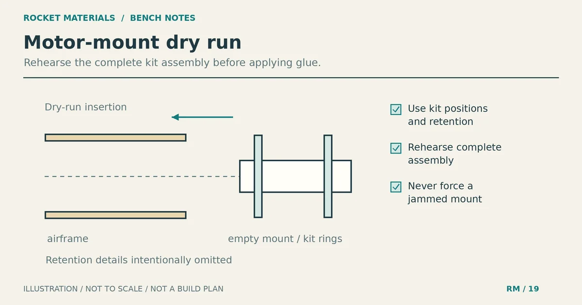
Model rocket motor mount: assembly and fit checks
A paper model rocket motor mount can slide easily during a dry fit and still stick halfway in once glue touches the rings. The awkward part is that the joint you need to finish is now inside the body tube. Avoid that problem before opening the glue: assemble the mount to the kit’s dimensions, let its joints dry, and rehearse the complete insertion.
This guide covers a commercial kit with a paper motor tube and centering rings. Your kit instructions set the component order, glue choice, installation depth and motor retention method. Use this workflow to prepare for those steps, not to substitute dimensions from a different rocket.
What belongs in the motor mount
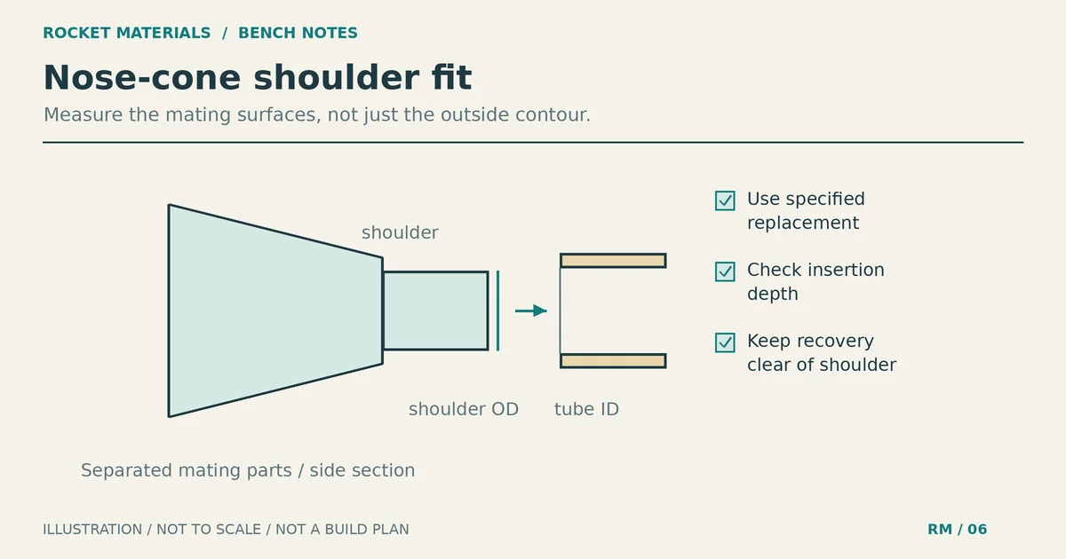
The motor tube holds the specified commercial motor. Centering rings connect that smaller tube to the airframe. Depending on the kit, an internal engine block limits forward travel, while a hook or other specified retainer keeps the motor in place. These parts have different jobs; a centering ring is not automatically an engine block.
The Estes Model Rocketry Technical Manual, under “Engine mounting methods,” describes both engine blocks and hooks. It also explains that inadequate retention can let a motor leave the rocket at ejection instead of deploying the recovery system. A mount that looks centered therefore still needs the correct retention hardware.
Lay out the kit parts beside the drawing. Identify the front and rear of the motor tube, each ring, the hook and any retaining sleeve. Some kits attach a recovery cord to the mount; others use a separate anchor. Do not add a mount attachment just because another builder’s example includes one.
Gather tools and mark every stop first
Have the kit directions, pencil, ruler, specified adhesive and a suitable glue applicator within reach. Fine sandpaper may be needed for permitted fit adjustments. Keep a paper towel handy and prepare a support that will hold the airframe in the required drying position without squeezing it.
Read through both mount assembly and installation before starting. Find the ring locations, hook slot position, engine-block depth and final mount position. Check which end each measurement starts from. A dimension measured from the front of the motor tube is easy to misread as one measured from the rear.
Transfer only the measurements in your instructions. Do not assume the aft ring or motor tube should sit flush with the body tube. If a dimension is missing or contradicts the supplied parts, ask the manufacturer before gluing.
Choose the adhesive by the kit directions rather than by a promise that one glue is always strongest. Our guide to adhesive choice and cured assembly weight covers that separate decision. Keep the specified adhesive ready for the installation step.
Assemble the model rocket motor mount outside the airframe
Follow the kit’s sequence for installing the hook and any sleeve, rings or engine block. Before adhesive touches a sliding part, confirm that it can reach its marked location. If the directions call for a knife-cut hook slot, use a cutting board and follow their location and size; children need appropriate adult supervision.
In Apogee’s motor mount assembly demonstration, Tim Van Milligan dry-fits the rings on the tube before applying glue. Around 2:01, he warns that trying to force rings over a glue-coated tube can crush it. That is a useful check even when your kit uses a different assembly order.
Each ring needs to reach its position without buckling the tube. Check part identity before removing material, and make only adjustments allowed by the manufacturer. For the dimensional side of centering-ring fit, see how tube dimensions affect motor mount fit. This is not a reason to enlarge a wrong-size ring until it seems usable.
As you glue the specified joints, keep the rings at their marks and check that flat discs are square to the tube. Add fillets where the instructions require them. Remove unwanted glue from the ring rims and motor passage before it hardens, without disturbing the intended bond.
If your kit uses an engine block, rehearse its placement with the supplied spacer or manufacturer-specified tool. Use the kit’s depth, not a general measurement copied from a manual. Remove a temporary positioning tool when instructed; it must not become a glued-in obstruction. Then allow the mount joints to dry as directed before inserting the assembly into the airframe.
Rehearse the whole insertion without glue
Test the completed, dry mount in the actual body tube. It should reach the specified position without heavy pressure. Testing loose rings alone is not enough: the assembled hook, sleeve or recovery attachment may change the fit.
Check the hook’s orientation relative to the fin markings. Estes’ manual places the hook between fin lines for access in its example. Your kit may have different requirements, especially if fins extend inside the airframe. Use the fin marking and alignment guide for marking technique, while keeping the kit’s layout.
During this dry run, decide where your hands will support the tubes and how you will recognize the final position. Make that reference visible before gluing. Remove the mount again without bending the hook or catching a cord.
If the kit anchors a recovery cord to the mount, route it as instructed so it cannot become pinched between a ring and the body tube. Van Milligan’s demonstration temporarily routes its cord out the rear during installation. Do not copy that detail unless it suits your kit’s attachment and routing instructions.
Place glue at the joints, then insert continuously
Phil Woolfson’s motor mount section in Peak of Flight 588 recommends measuring where the rings will contact the body tube and applying glue there. He also warns that pausing during installation can leave the mount stuck in the wrong position. Estes gives the same smooth-motion warning under “Install the engine mount.”
For a kit using that installation method, prepare the applicator to reach the specified joint locations. A visible depth mark on the applicator can help you place the glue where intended. Confirm the reach during preparation rather than discovering that your tool is too short with wet glue already inside the tube.
- Set the dry mount beside the airframe in its rehearsed orientation. Keep the final-position reference in view.
- Apply the adhesive where the kit directs, with coverage appropriate to its instructions. Keep unintended glue out of the motor passage and away from moving retention parts.
- Insert the mount in one smooth, continuous motion to the specified stop. Do not pause halfway to fetch a ruler or check the drawing.
- Confirm the final position and hook orientation immediately, then support the airframe as directed while the joint dries.
Continuous insertion does not mean forcing a jam. It means preparing well enough that you do not need to stop an otherwise smooth movement. Do not thin the adhesive, change its formulation or flood the tube to compensate for a failed dry fit. There is no universal glue quantity or insertion time for every paper mount.
If the mount sticks or finishes in the wrong place
A mount that catches during the dry run needs attention before glue. Look for an incorrect part, a glue bead on a ring rim, a projecting sleeve or a trapped cord. Inspect the paper tubes for dents or distortion. Do not sand damaged tubing until the assembly happens to slide.
If the mount grabs during the glued insertion, stop escalating the force. Hammering, levering or squeezing can damage the tubes or loosen joints you can no longer see. A partly installed mount is not ready to fly because its accessible rear joint looks neat.
Leave the model unflyable and ask the kit manufacturer how to proceed. A wrongly positioned block, damaged tube or mount stuck at the wrong depth may require replacement parts and rebuilding. This guide does not recommend improvised load-bearing repairs or a different motor to accommodate the mistake.
Inspect the cured mount before finishing the rocket
After the required drying period, compare the installed assembly with the kit drawing. Check that it remains at the intended depth, the visible joints are intact and the hook or retainer can operate without interference. Inspect the motor passage for hardened glue or misplaced components.
Check motor fit only as the kit and motor manufacturer direct, after the adhesive has cured and without an installed starter. Use a recommended, unmodified commercial motor. It must seat correctly and engage the specified retention system without excessive force; do not alter the motor casing to make it fit.
Before moving on, resolve any uncertain depth, obstruction or damaged joint. For the next mount, have the final-position mark and glue applicator ready before opening the adhesive. Rehearse with the completed assembly, not just the loose parts.