Rocket centering rings: dry fit, square and glue them
A centering ring can slide over the mount tube and still bind inside the rocket. Or it can fit both tubes but sit at an angle. Rocket centering rings need separate checks for each mating surface, then an alignment check before the glue sets. A bigger fillet can hide a poor fit instead of fixing it.
Start with the rings supplied or specified for your kit. Their material, thickness, number and locations belong to that design. The workflow below covers dry fitting and ring workmanship, not a replacement motor-mount design. Your kit instructions take priority, including adhesive choice and any parts that must remain removable until later.
Check the hole and outer edge separately
The inner opening fits over the outside of the mount tube. The outer edge fits inside the airframe. Neither fit tells you whether the other is right. If the parts came from different product lines, check their identity before sanding. Our tube wall thickness and motor-mount fit guide handles the dimensional comparison; this page starts with the actual parts on your bench.
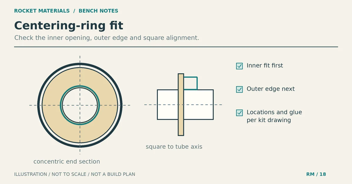
Concentric means the inner opening and outer circle share a center. Square means a flat ring’s face is perpendicular to the mount tube’s axis. An off-center opening can hold the mount sideways even when the ring face is square. A tilted ring can have a centered opening but still bind during assembly.
Apogee’s Newsletter 126 explains concentric circles and sanding the inner opening before the outside edge. It is a historical construction article, not a current specification for every ring. Do not copy its sample clearances or reinforcement changes into an unrelated kit.
Prepare before removing material
Read ahead far enough to find the ring locations, orientation and clearance requirements. A notch may accommodate an engine hook; another opening may belong to a recovery attachment. Do not make an extra notch because the parts seem easier to assemble that way.
Set out the actual tubes and rings, a pencil, ruler, fine abrasive suitable for the ring material, and a small square if the ring has a flat face. A smooth dowel can support abrasive for the inner opening. Keep the kit diagram nearby rather than relying on marks remembered from another build.
Inspect the tube ends and ring edges first. A crushed tube mouth, torn paper layer or warped ring needs attention before you can judge fit. The body tube size chart helps identify standard tube families, but the label cannot confirm the fit of a delivered part.
For a paper-and-wood kit that permits sanding, use light hand pressure. Composite rings need their manufacturer’s preparation and dust-control instructions; this paper-ring workflow is not a reason to sand fiberglass indoors without controls. Follow adhesive handling warnings too. Keep motors and starters out of this bench operation.
Dry-fit rocket centering rings without forcing them
Fit the inner opening first
Try each ring on the mount tube without glue. Keep it square as it moves toward its intended location. If it catches, stop and inspect the contact rather than twisting harder. Check for an interfering hook or other hardware, an edge burr, and damage to the tube.
When the instructions permit fitting by sanding, support the ring and make a few light passes around the inner edge with abrasive on a suitable dowel. Move around the opening instead of scraping one side into a slot. Remove loose dust, then try it on the actual tube again. Apogee describes this inside-first approach and repeated fit checks in Newsletter 126.
Stop removing material once the ring reaches the specified position with controlled hand pressure and without scraping or crushing the tube. Do not aim for a visibly loose opening. If the ring rocks sideways or has a substantial gap, further sanding cannot restore the missing material; ask the kit maker about a replacement.
Fit the outer edge next
Test the ring at the airframe opening while you can still retrieve it. Avoid pushing a loose ring deep inside a long tube. If it binds, inspect whether the interference follows the ring or a damaged area of the tube. Gentle changes in orientation can help locate contact, but do not force the ring through an oval or crushed section.
For a minor oversize edge on a ring that the maker allows you to sand, keep the face supported and work lightly around the circumference. Recheck often. Watch for an uneven annulus, the band of material between the hole and outside edge. Removing a large amount from one side can shift the effective center of the mount.
Apogee shows a coupler-supported sanding method for handmade rings to help keep the outer edge circular and reduce paper delamination. That method is useful context, not an instruction to tack-glue your supplied ring to a spare coupler. For a badly uneven kit part, a correct replacement is preferable to reshaping it by eye.
Hold flat rings square at the kit marks
Mark each ring location exactly as the kit shows, including which face meets the mark. A dimension to the forward face is different from one to the aft face. Changing that reference shifts the installed ring even if your ruler reading is correct.
At the dry-fit stage, place a small square against the straight side of the mount tube and the flat ring face. Check at several points around the tube. The square should touch without levering the ring into position or denting the tube. This is a visual workmanship check, not a certified angular tolerance. Apogee’s Newsletter 588 gluing guidance describes using a square for flat centering discs.
A compatible alignment tool can hold a ring during positioning. Estes’ centering-ring aligner instructions, revision 1-26, show a thin glue bead followed by moving the ring to its final position with the tool. Use a tool that fits the actual tube, and follow its removal sequence so it does not become part of the joint. A jig does not correct an off-center hole.
Glue the contact surfaces, not the fit problem
Use the adhesive your kit specifies for its joint materials. Estes’ currently linked Alpha instructions call for test fitting before glue and sanding as needed; that kit lists carpenter’s glue. This is an example of kit-specific direction, not a prescription for plastic or composite rings. Our rocket adhesive guide covers material compatibility without treating extra glue as a performance upgrade.
If the instructions call for surface preparation, do it only at the intended bond areas. Apogee discusses lightly scuffing slick paper tube surfaces for woodworking glue in Newsletter 588. Do not sand through the tube’s outer layer or change its diameter to make an incorrect ring fit.
Follow the specified ring-gluing sequence. For the Estes aligner method, the ring starts short of its final location, receives a thin bead immediately behind that position, then moves forward into place. Check its mark and alignment while adjustment is still possible. Remove the tool as directed. Once the joints have set, those tool instructions call for fillets on both sides of the rings. Your kit may require different access or timing.
Before the ring assembly goes inside the airframe, identify where each outer edge will actually contact its wall. Glue depth follows those contact locations and the kit’s final mount position; it is not automatically the depth of the visible rear ring. Rehearse the reach of an applicator without glue and mark the required depth on it. Apogee illustrates this contact-depth planning in Newsletter 588.
Keep specified hook movement and recovery clearances open. If your kit places a cord near a ring, check its approved routing before closing access. The shock cord mounting guide explains why attachment details must follow the actual airframe design. Do not drill a new ring hole or move the anchor to solve a clearance problem.
When a fit check fails
- A ring catches only at the tube mouth: inspect the mouth for crushing or a lifted layer before sanding the whole ring smaller.
- The inner opening fits but the outside binds: work on the outer fit only after confirming the correct ring and airframe.
- A ring wobbles before glue: stop. Check part identity and ask about replacement rather than bridging a substantial gap with glue or tape.
- A flat ring tilts as you position it: check for uneven contact or hardware interference, then repeat the square check before the adhesive sets.
- A ring is torn, delaminated or cracked: do not hide the damage under a fillet. Obtain the manufacturer’s repair or replacement direction.
Inspect before the rings disappear inside the tube
Confirm every ring matches the intended location and orientation, the flat faces are square, and the mount sits centered in the dry-fitted airframe. Check accessible bonds for missed areas and unwanted glue on moving parts. Let the adhesive cure according to its own instructions and the kit; a joint that feels firm is not necessarily ready for the next operation.
Record anything you cannot inspect once the airframe closes. Ring fit and clean joints do not establish a motor rating or approve the completed rocket for flight. If the parts still require force, wobble or show damage, resolve that with the kit maker before continuing. Compare the dry assembly with the kit drawing once more before you close access to the rings.